Deepwater Horizon Oil Spill
Pipeline Break -
Solution
By
Troy Laclaire

Deepwater
Horizon Spill Concept
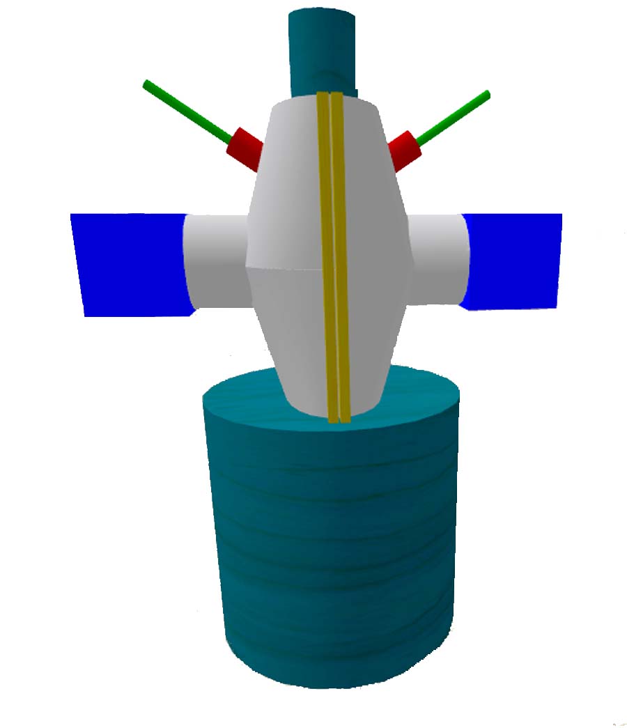
Description of Components
1. Grey: This would be
formed pipe/steel that would be placed around the old pipe.
2.
Yellowish: This area would be the "join" points, and
can be either welded or predrilled for bolts. They are slightly
spaced so that a very tight seal can be made.
3. Red: One
way tube for puncture pipe.
4. Green:
This would be a "spike" or "drill" that would be used to puncture
the old pipe to allow oil to flow into the new area. It has a
larger piece behind the spike, so that once pressure starts to build
up it self seals around the "red" tube.
5. Blue
box: This would be where the valve system would be
placed to connect new pipe to, as well as to control pressure.
6. Not
shown: Cap for top, which would be put in place in
an open position and then once ready would be closed to cut the
current pipe and seal the whole system. This is an extremely simple
concept, as it is somewhat based on how the tops to sports arenas
work.
Final
image: This final 3D graphic rendering shows how the
whole thing would fit on top of the "blow out preventer" that failed
during this spill, and has to be built in place, by the deepwater
robotic tethered submersibles that are on site and used in deep sea
oil and gas drilling operations which are standard in the oil and
gas exploration industry.
Note on 3D Renderings depicted:
These graphic images are missing the final
top piece or component which would have cut the old pipeline and sealed
the system in on itself. For more details on this solution you may
contact the Online Think Tank to speak with the design engineer on this
project or further adaptations needed for your challenges or
applications.
|